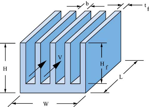
Heat Sink Fin Spacing Calculator. Fin Height - between 3-100mm. For purposes of illustration these equations were used to estimate heat sink thermal resistance for a 50 x 50 mm aluminum heat sink. This tool is designed to calculate junction temperature of an electronic device typically power devices given four parameters. UNCLASSIFIED Approved for public release.

UNCLASSIFIED Approved for public release. Program based in Microsoft Excel calculates the optimal fin spacing and efficiency a whole heat sink efficiency heat dissipation and the maximum heat sink temperature based on the input parameters fin length fin height fin thickness fin material maximum allowable temperature and ambient temperature. The maximum ambient temperature the devices junction-to-package thermal resistance the thermal resistance of the heat sink and the power applied. 560 K 38C Estimated fin temperature rise. The thermal resistance of the heat sink and temperature of the power source is calculated. Heat Sink Calculator 1.
100F 555C Gravity322 ftsec 2.
Steady state or transient solutions are available for forced are natural convection. Fins are used to increase heat transfer area and provide a cooling effect. If you were to try to optimize the heat sink dimensions the spacing between the fins would be a very small value since the air velocity and hence rate of cooling increases with decreasing fin spacing. 9 Temperature at the base of the heat sink as a function of fin spacing 12 10 Conductance of the heat sink for different fin thicknesses 13 11 Temperature at the base of the heat sink for different fin thickness 13 12 Heat transfer from the heat sink for different fin thicknesses 14 13 Conductance of the heat sink for different fin height 14. Fin Pack Information While fin height can vary considerably by application we typically see figures in the 10-35 mm range. Heat Sink Calculator 1.